知识中心
惠斯登电桥
本页内容更新于- 1. How Does a Wheatstone Bridge Circuit Work?
- 2. The Versatility of Wheatstone Bridge Circuits
- 3. Wheatstone Bridge in a Load Cell
- 5. Wheatstone Bridge and Load Cell Wiring
1. How Does a Wheatstone Bridge Circuit Work?
A Wheatstone Bridge is an electrical circuit used for precisely measuring resistance. It consists of four resistors arranged in series along two parallel arms bridged by an ammeter or voltmeter.
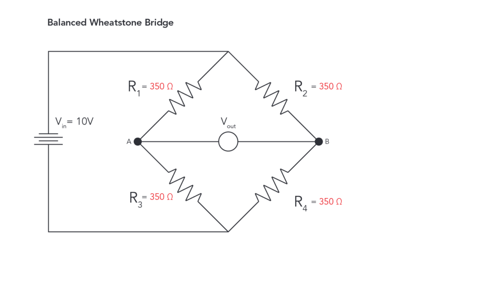
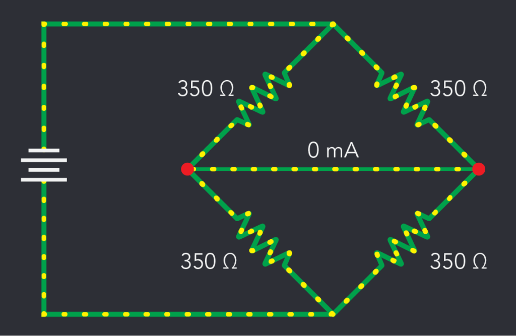
| This bridge circuit is “balanced”. The current flowing in the R1 / R3 branch is equal to the current flowing in the R2 / R4 branch because all resistors are equal in their resistance values. There is no voltage difference between points A and B potential difference between the midpoints will be zero. For a bridge to be balanced (no output voltage, Vout = 0) |
 |
|
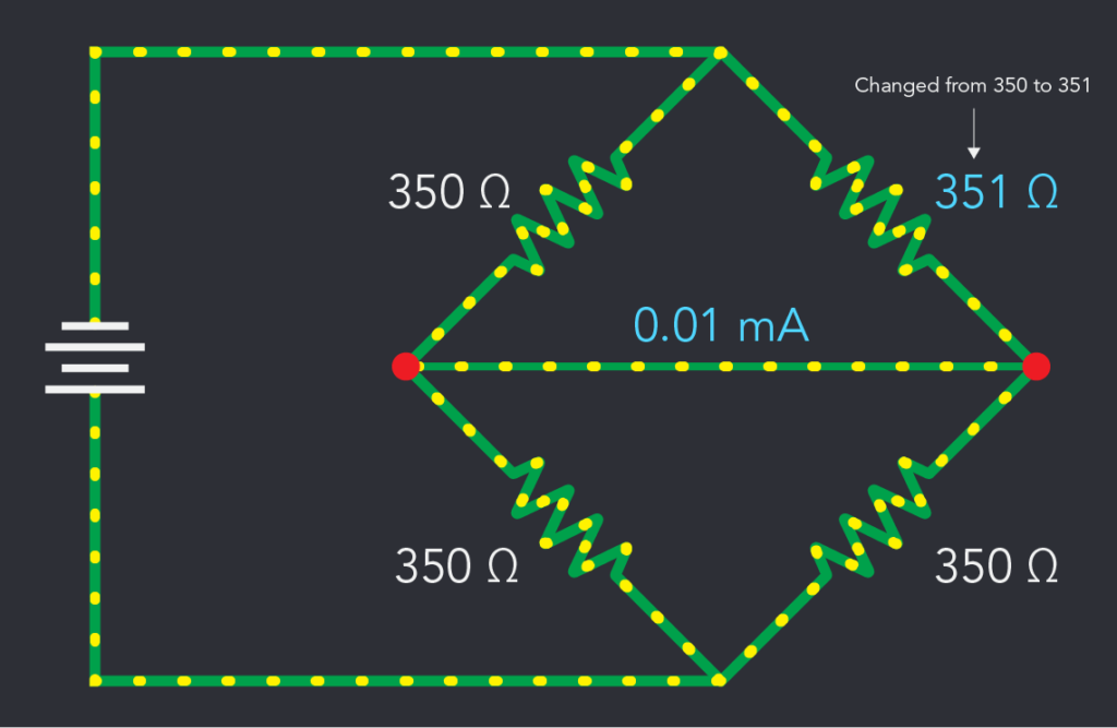
A change in resistance (Ω) in one of the resistors will result in a measurable current that flows through the ammeter. This bridge circuit is now “unbalanced”. This imbalance causes the ammeter to register a voltage, indicating a change in resistance. |
 |
|
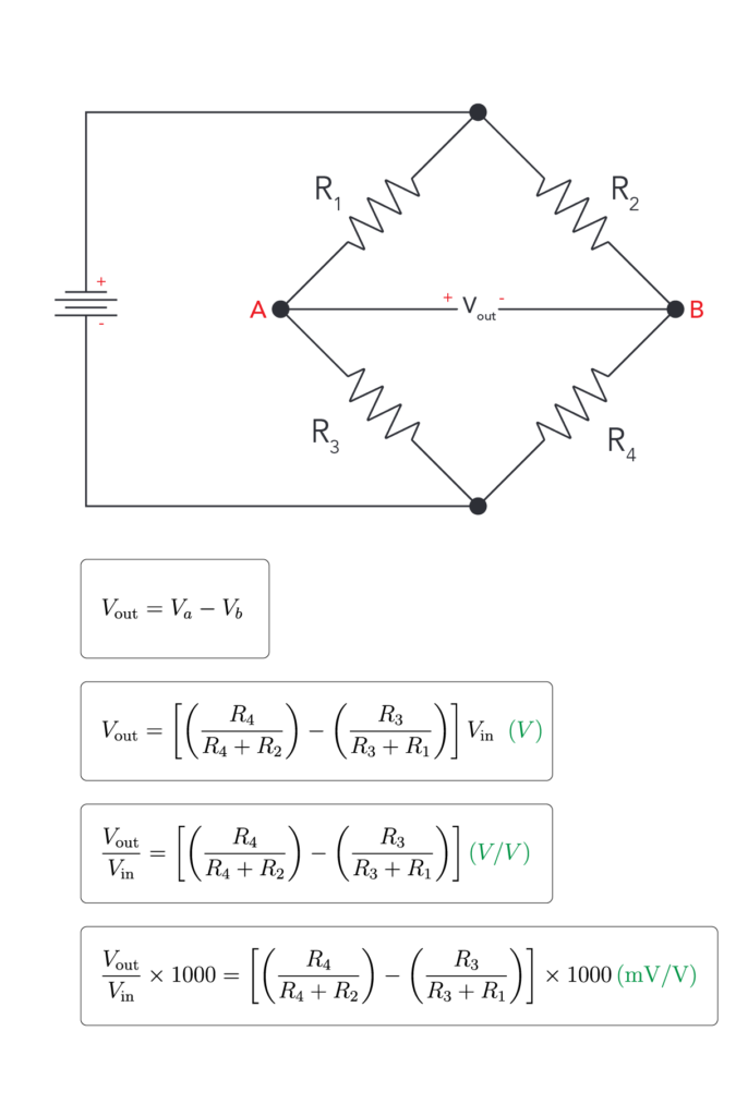
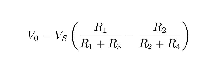
1. Wheatstone Bridge Output Voltage (Vout):
This equation calculates the voltage difference across the bridge, which is used to determine the strain based on changes in resistance. 2. Strain Gauge Factor (GF):
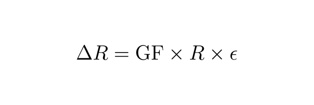
Where ΔR is the change in resistance, R is the original resistance, and ϵ is the strain (change in length divided by original length. The Gauge Factor relates the change in resistance of the strain gauge to the mechanical strain applied 3. Strain (ϵ):
Where ΔL is the change in length and L is the original length. This equation defines strain as the relative change in length of the material being measured. 4. Change in Resistance (ΔR):
Using the gauge factor and the strain, you can calculate how much the resistance of a strain gauge changes when a strain is applied. |
 |


2. The Versatility of Wheatstone Bridge Circuits
Wheatstone bridge circuits are utilized in various applications beyond strain gauges and load cells, thanks to their ability to precisely measure electrical resistance changes. Some common applications include:
1. Temperature Sensors (Thermistors and RTDs): Wheatstone bridges are used with temperature-sensitive resistive devices like thermistors (thermal resistors) and Resistance Temperature Detectors (RTDs) to measure temperature changes with high accuracy.
2. Humidity Sensors: Some humidity sensors use resistive or capacitive materials that change properties in response to humidity. A Wheatstone bridge can measure these changes, converting them into a readable electrical output indicative of moisture levels.
3. Light Sensors (Photoresistors): In light-sensitive applications, photoresistors (whose resistance changes with light intensity) are incorporated into Wheatstone bridge circuits to create highly sensitive light detection systems.
4. Force Sensors: Similar to load cells but used in different contexts, force sensors employing Wheatstone bridges can measure forces such as impact, touch, or interface pressure between surfaces.
5. Gas Sensors: Certain gas sensors operate with materials that change resistance when exposed to specific gases. Wheatstone bridges can measure these resistance changes, allowing for the detection and quantification of gas concentrations.
6. Piezoelectric Sensors: Used for measuring dynamic changes like vibration and acceleration, piezoelectric sensors can be part of a Wheatstone bridge to convert mechanical stress into measurable electrical outputs.
These applications leverage the Wheatstone bridge’s sensitivity to small resistance changes, enabling the precise measurement and monitoring of various physical and environmental conditions.
3. Wheatstone Bridge in a Load Cell
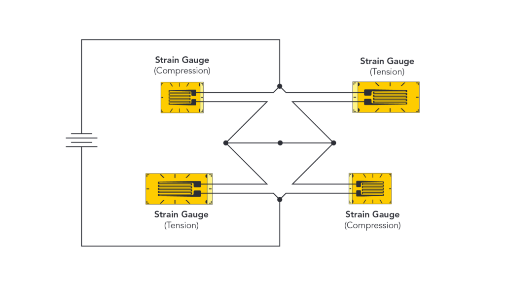
| A strain gauge is simply a variable resistor—a resistor that is able to have its electrical resistance adjusted. In a load cell’s Wheatstone Bridge, one or more of the resistors are strain gauges. When the bridge circuit is balanced, with all resistors at the same electrical resistance, a baseline can be established. A balanced circuit with zero output detected by the ammeter indicates that there is no load being applied to the load cell. With a zero baseline established, the load cell can thus accurately measure applied loads. |
 |
 |
Strain gauges are bonded to strategic locations onto the load cell element (a metal block). Here, a simplified example (see: Figure 3.1) shows how a load cell can be assembled from four strain gauges applied in a Wheatstone Bridge circuit to the element. Converting the ammeter readings to pounds or kilograms effectively creates a rudimentary scale, capable of providing measurements of weight. |
5. Wheatstone Bridge and Load Cell Wiring
The Wheatstone Bridge is at the core of how a strain gauge load cell is wired. The four primary wires that comprise a load cell cable correspond directly to the Wheatstone Bridge circuit. Understanding how the circuit is powered and where a measurable signal is the foundation for understanding load cell wiring and troubleshooting. The following section on load cell wiring will introduce load cell wiring.