知识中心
传感器故障处理
本页内容更新于2024年10月09日Introduction to Troubleshooting Load Cells
Following to this guide will help identify common load cell issues, helping to ensure reliable and accurate measurements. This guide outlines systematic tests for diagnosing issues with load cells. If any of the abnormalities are revealed, it indicates a malfunction.
The key to effective troubleshooting is to take a step-by-step approach. Start by isolating the problem. Recording the information, taking pictures and videos are also very helpful for professionals that are engaged to help resolve the issue.
This is intended to be a general all-purpose troubleshooting guide.
- Always refer to the specific data-sheet and manual of the product.
- Seek professional services if possible.
- Do NOT attempt to troubleshoot any systems that could pose a safety issue unless fully qualified and authorized.
The following instructions for visual inspection and electrical tests is designed to be performed sequentially. It is intended to help narrow down or identify the issue.
- 1. Visual Inspection
- 2. Electrical Tests
- 3. Guide to Electrical Tests for Load Cell Troubleshooting
- Zero Balance Test:
- Bridge Resistance Test:
- Bridge Resistance Test (Overload Verification Test):
- Resistance to Ground Test:
- Insulation Resistance Test:
- 4. Requesting Professional Assistance
1. Visual Inspection
a) Cable Integrity:
Examine the load cell cable for visible damage such as cuts, abrasions, signs of crushing damage, rodent damage, and exposed wires, which could compromise functionality.
b) Load Cell Condition:
Inspect the load cell for any physical anomalies like dents, deformations, cracks, corrosion, or other unusual wear, particularly in the load-bearing areas. Load cells are by design highly sensitive sensors and small anomalies can indicate damage that can impact system performance.
c) Flatness Check:
For single-point and double-ended beam load cells, verify the flatness using a straightedge and or level to detect any visible deformations. Even slight deformations indicate overloading or shock loading and can significantly impact accura
2. Electrical Tests
Any test result that does not match the parameters in the datasheet/calibration certificate of the load cell indicates a problem.
a) Zero Balance:
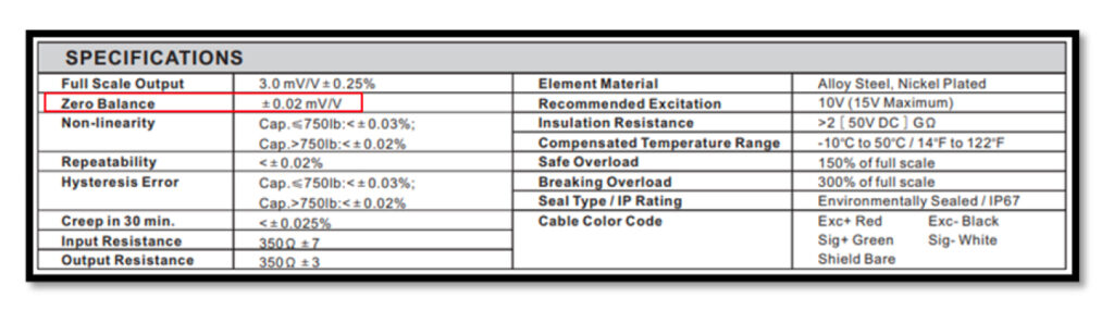
With no load on the cell, connect it to a stable power source. Measure the output voltage with a multimeter, convert to mV/V (output in mV divided by input in V), and compare against the load cell’s calibration certificate to ensure it’s within specification.
b) Zero Return:
After checking zero balance, load the cell to 50-100% capacity for 5 seconds, then remove the load. The mV/V output should return to within the specified tolerance, indicating proper function.
c) Insulation Resistance:
Measure the insulation resistance between the wire leads and the load cell’s metal body using a multimeter. A reading below 2 GΩ suggests inadequate insulation, whereas an ideal reading exceeds 5 GΩ.
d) Resistance Measurements:
Check the input and output resistance values using a multimeter with at least 0.025 Ω accuracy. Values diverging by more than 0.1 Ω from the calibration certificate indicate a fault.
e) Strain Gauge Resistance:
Individually test each strain gauge’s resistance, referencing the load cell’s wiring diagram for correct testing points. Discrepancies here can pinpoint specific issues within the strain gauge array.
f) Input/Output Resistance:
Resistances exceeding 3 kΩ typically indicate damage from electrical surges or lightning strikes. Confirm with the calibration sheet for expected resistance values.
3. Guide to Electrical Tests for Load Cell Troubleshooting
Zero Balance Test:
Conduct this test if:
- Instrument is showing Over-Range Error exceeding the total rated capacity of the load cell.
- Instrument does not respond until a specific and consistent load is applied.
- Other load cell symptoms that suggest damage, such as a constant Zero Shift.
Instructions:
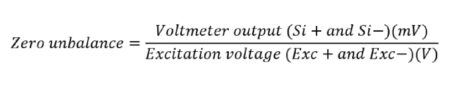
Remove any dead load on the load cell and make sure there is nothing on the load cell. Connect the Ex+ and Ex− leads of the load cell to a reliable and known voltage supplier (5-15VDC). Measure the Voltage between the Si+ and Si− using a Voltmeter (mV range). Keep the load cell at no load condition when take the measurements.
Then, calculate the zero unbalance of the load cell as Voltmeter output(mV)/supply voltage.
Compare the results against the zero balance specifications on the load cell datasheet. For example:
Result 1: The zero unbalance is within the specification.
Conclusion: Load cell is functioning properly. No action needed.
Result 2: The zero unbalance is exceeded the specification.
Conclusion: The load cell has been stressed/overloaded, and the elastic range (useful range) of the load cell has been altered. In this case, Anyload recommends replacingthis load cell to get the best performance from the weighing system. And also,it is recommended to closely monitor the system to identify the root cause foroverloading to prevent this issue happening again in the future.
Bridge Resistance Test:
Conduct this test if:
- Instrument displays an ADC (analog-to-digital converter) Error, indicating potential issues with signal conversion.
- Load cell suspected to be malfunctioning due to an open signal or short circuit.
- Signs of a damaged load cell, such as unexpected zero shifts or inconsistent readings.
Instructions:
Use an Ohmmeter/multimeter and measure the input and output resistances of the load cell.
Input resistance – Resistance between Ex+ and Ex−
Output resistance – Resistance between Si+ and Si−
Compare the test results with the specifications on the load cell datasheet.
Result 1: The resistance readings are both within the published specs.
Conclusion: Load sensor is functioning properly. No action needed.
Result 2: The measured resistance readings are outside of the published spec.
Conclusion: The load cell is damaged and must be replaced.
Bridge Resistance Test (Overload Verification Test):
Conduct this test if:
- Instrument is showing an Over-Range Error where the displayed load exceeds the total rated capacity of the load cell(s).
- Instrument does not respond until a specific and persistent load is applied to the scale.
Instructions:
Use an ohmmeter/multimeter and measure the terminal resistances below.
Ex+ to Si+
Ex+ to Si−
Ex− to Si+
Ex− to Si−
Result 1: The resistance readings are all almost equal.
Conclusion: Load sensor is functioning properly. No action needed.
Result 2: Two of above values are higher and almost equal while other two values are lower and almost equal.
Conclusion: Load cell has been overloaded.
Resistance to Ground Test:
Conduct this test if:
- Readings are affected excessively by noise, is unstable.
- Instrument displays an ADC Error.
Instructions:
- Disconnect power to the junction box and the load cell from the junction box.
- Tie the load cell bridge circuit wires and Shield together (Ex+, Ex−, Si+, Si−, SHIELD)
- Measure the resistance using an ohmmeter between the aforementioned tied terminal and the load cell body (touch the tip of the ohmmeter to the metallic element of the load cell).
Result 1: Results show Open Signal, indicating no continuity between the two terminals.
Conclusion: Load sensor is functioning properly. No action needed.
Result 2: Results show Close Signal, indicating a resistance value between the two aforementioned terminals.
Conclusion: Load cell is exhibiting a resistance to ground, which can cause noise and other issues. The load cell must be replaced.
Insulation Resistance Test:
Conduct this test if:
- Readings show excessive noise, unstable output.
- Instrument displays an ADC error.
Instructions:
- Disconnect power to the junction box, load cell from the junction box.
- Tie the load cell bridge circuit wires (Ex+, Ex−, Si+, Si−) together.
- Measure the resistance using an insulation meter (Megger) Ohmmeter between the following terminals:
- Bridge wires to Body (load cell element).
- Bridge wires to Shield.
- Shield to Body.
Result 1: Results show Open Signal, indicating no continuity between any of the above mentioned terminals.
Conclusion: Load sensor is functioning properly. No action needed.
Result 2: Results show Close Signal, indicating a resistance value between the any two aforementioned terminals.
Conclusion:
- Bridge to Body failure — Bridge circuit is leaking to the Body, may be due to moisture ingress into the circuity area.
- Bridge to Shield failure — Likely to be a cable issue, especially in the cable entry area.
- Shield to Body — Likely to be an issue in the cable entry area as the Shield is touching the Body.
*Any of the 3 failures suggest a manufacturing defect and requires replacement of the load cell.
WARNING: When using a megger do not exceed the published insulation resistance voltage.
4. Requesting Professional Assistance
While the basic steps outlined above can help identify common issues with weighing systems, some problems may require the expertise and equipment of a professional scale service company. Attempting to resolve complex issues without the necessary qualifications can lead to extended downtime, additional complications, and unnecessary risk to equipment and safety.
Professionals in scale service possess the expertise, tools, and experience to diagnose and resolve issues efficiently. They can provide comprehensive services, from calibration and maintenance to repairs and parts replacement.
We understand the urgency of resolving scale issues promptly to avoid operational disruptions. That is why we offer a global network of qualified service providers through our “Find A Dealer” page. No matter where you are in the world, our platform can connect you with a qualified professional ready to assist with your weighing system needs.